Line6 HX Stomp 3.5mm MIDI Mod
- James

- Jul 23, 2020
- 2 min read
Updated: Feb 16, 2021
Needles to say, the HX Stomp is a great pedal, but we want to make a great pedal even greater.
Why we wanted to use 3.5MM jacks
We're not big fans of the DIN5 MIDI jacks because of the size.
There are plenty of 3.5m cables out there in the market, and finding one with a right-angled plug is easy.
We've also got a 3.5mm MIDI splitter box with us, and we want to connect our devices entirely with 3.5mm cables.
The Mod
I would rate difficulty of this mod a 8/10 - simply because you're modifying a USD600 device. If you're not comfortable with DIY, you'd probably want to skip this mod.
The steps, otherwise, should be ok. We probably took about 20-30 minutes end to end to complete the mod. You just need to drill one hole in the enclosure and solder 2 wires.
Do this modification at your own risk.

First things first - the backplate needs to be removed.

Next, we used a nut driver to remove the nuts from the 6.35mm jacks.


Next, I used a small flat-head screw driver to slowly pry the PCB out.

The boards are connected together with a ZIF cable and connectors. The flap on the ZIF connector can be lifted so that the cable can be removed. The part to lift is the black flap that is closer to the cable.


We used a center punch to mark the drill spot. We drilled about 15mm away from the center of the MIDI IN hole.


After which, we used a 3mm drill bit for the pilot hole first, before using a 6.5mm drill bit. I stuck some tape to over the circuit board to prevent any metal shavings from dropping in.


I just used a generic 3.5mm stereo jack I found in the shop. Whichever 3.5mm jack you decide to use, do make sure that it isn't so wide such that you can't fit the circuit board back (there is limited space between the MIDI IN jack and the electrolytic capacitor beside it). Also take note that the spacing on the threaded part of the jack needs to be long enough so you can screw the nut in. Ours almost could not be used, but the nut managed to get some bite on the thread.
We do have some of these on order so we'll probably change it out if need be.

Do take note that the the Tip needs to go to the MIDI Pin 5 and the Ring needs to be soldered to Pin 4. I just soldered it directly to the jack. The sleeve should be left unsoldered.

Once you screw in your 3.5mm jack, you're almost done! Just put everything back together and close it up. Make sure that the ZIF cable is aligned before closing the flap.

When putting back the circuit board, push in the side where the USB port is first.You might need to use a bit of force to push everything back in.

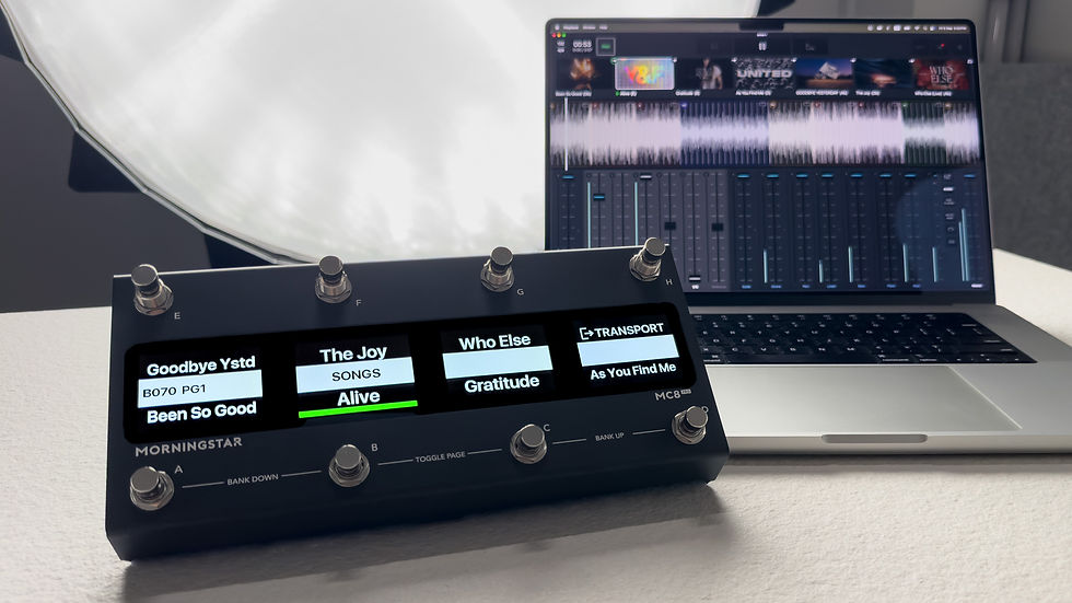
And there you have it! Works perfectly with our Morningstar 3.5mm MIDI splitter.
Keep making awesome music!
The Morningstar Engineering Team